Wednesday, March 18, 2015

Monday, March 16, 2015
Question bank for PTT - 2 MAP (2014-2015)
- Explain the following instructions
- i. ROR
ii. MOVSB
iii. STD - iv. ROL
v. CMPSB
vi. CLC - Explain the assembler directives ASSUME, DW, EVEN.
- Write the code segment for multiplying two 8 bit numbers.
- Differentiate between FAR and NEAR calls (Any 6 points)
- Explain all 4 tools for development of Assembly language programming tools.
- Explain Recursive and reentrant procedure
- Define Macro. WAP to solve P = x2 + y2 using macro
- Write an assembly language program to find ODD/EVEN numbers in the array.
- Write an assembly language program to transfer block of data from one segment to another.
- Write an assembly language program to compare two strings and print on console whether strings are same or not.
- Explain the assembler directives proc, macro, and segment.
- Write the code segment for subtraction of two 8 bit numbers.
- Explain the concept of FAR CALL
- Draw the timing diagram of memory read operation in minimum mode
- Explain Recursive and reentrant procedure
- Define Macro. WAP to solve P = (X+Y)*(A+B)
- Write an assembly language program to find positive and negative numbers in an array.
- Write an assembly language program to count the number of ones and zeroes in an eight bit number
- Write an assembly language program to compare two strings in two different segments and print on console whether strings are same or not.
- Explain the concept of NEAR CALL
- Define Macro. WAP to solve P = X2+Y2
- Draw the timing diagram of memory read operation in minimum mode
- Draw the timing diagram of memory read operation in maximum mode
- Draw the timing diagram of memory write operation in maximum mode
- Write an assembly language program to find the number of ones and zeroes in a given 8 bit number
Saturday, February 21, 2015
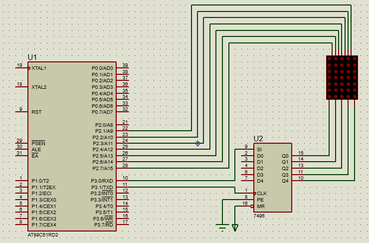
Single Dot matrix display interfacing with 8051 based Microcontroller
Wednesday, March 19, 2014
Question bank EDS
a.
Draw the structure of RS232 and explain any 4
pins
b.
Describe in detail any 3 software development
tools
c.
Explain the concept of DMAC with neat diagram
d.
Draw the structure of port 0 and explain its
operation in input mode
e.
Compare i2c and can bus
f.
Explain the different services of RTOS
g.
List
the sequence of events that take place while executing an interrupt
h.
List the serial communication protocols and
explain I2C bus with neat sketch
i.
Explain in detail memory organization of 8051
j.
Draw the formats of TCON and TMOD registers and
explain the bits
k. Identify the Addressing modes
for the following instruction
MOV A,#20H
MOV 80H,A
MOV @R1,35H
MOV A,R0
l.
Draw the interfacing diagram to interface LCD
with 8051 and write a program in C language to display “WELCOME” on lcd screen.
m.
Explain starvation and deadlock in detail
n.
Draw the pin diagram of 8051 and explain each
pin
o. Draw and describe Harvard
Architecture and compare with Princeton architecture
p. Describe any 4 bit handling
instructions of 8051
q. Draw the format of SCON and
describe its functionality
r.
Draw
PSW of 8051. State the function of each bit
s. Divide the data in RAM location
13H by the data in RAM location 14H. Then restore the original data in 13H by
multiplying the answer by the data in 14H. Use assembly language for 8051
controller.
t.
Write a program in C language to transfer MSBTE
serially at 9600 baud rate with 1 start bit and 1 stop bit
u. Enlist the various interrupts of
8051 with their priorities, vector locations and cause of interrupts
Question bank for MAP
a. Explain
the following assembler directives:
1. ASSUME
2. DUP
3. ENDS
b. Differentiate
between near and far calls
c. Draw
neat labelled architecture of 8086
d. Explain
any 3 addressing modes of 8086 with example
e. List
the steps in physical address calculation with example
f.
Define procedure and explain the directives used
in the procedure
g. How
queuing speeds up processing of 8086 operations (explain with example)
h. Explain
CALL and RET instructions
i.
State the function of the following pins
1. INTR
2. BHE#
3. DEN#
j.
Draw the flag register of 8086 and explain any 3
flags
k. Draw
neat labelled diagram of octal latch 74LS373 and explain the same
l.
Explain the following instruction 1. XLAT 2. XCHG
m. Explain
the following instructions 1. AND 2.
TEST 3. LEA
n. Write
an assembly language program to print the reverse of string
o. Write
an assembly language program to transfer 10 bytes of data from one memory
location to another. Also draw flowchart
p. Write
a program using procedure to find the factorial of a number
q. Write
a program to add, subtract two BCD numbers
r.
Draw the interfacing diagram of octal latch with
8086 microprocessor
s. Draw
the maximum mode diagram of 8086 with proper labelling
Thursday, February 27, 2014
PST Questions
PST
questions:
1. List the ports available in 8051.
State alternate functions of port 3
2. Draw the structure of Port 0 and
explain its operations in input mode
3. Draw the pin diagram of 8051 and
state function of each pin
4. Write a program in C language to
transfer the message “WELCOME” serially at 9600 baud rate, 8 bit data, 1 start
bit and 1 stop bit
5. List the sequence of events that
take place while executing an interrupt
6. Draw the functional block diagram
of 8051
7. Draw the formats of TCON and TMOD
registers and explain the bits
8. Write a program in C to get data (AA
H) from Port 0 and send it to port 1 of 8051
9. Identify the Addressing modes for
the following instruction
a.
MOV
A,#20H
b.
MOV
80H,A
c.
MOV
@R1,35H
d.
MOV
A,R0
10. Write a program in C to generate
square wave on P1.2 bit, use interrupt for timer
11. Draw and describe Harvard
Architecture
12. Explain in detail memory
organization of 8051
13. Explain in detail mode 0 of a
timer available in 8051
14. List the addressing modes of 8051.
Also give example of each mode
15. Draw the structure of Port 0 and
explain its operations
16. Give an overview of 8051 family
17. Write a program in C language to
transfer letter M serially at 4800 baud rate, 8 bit data,1 stop bit
18. Describe any 4 bit handling
instructions of 8051
19. Draw the format of SCON and
describe its functionality
20. How many timers/counters are
available in 8051. When are they used? What is the initialization instruction
21. Draw PSW of 8051. State the
function of each bit
22. Enlist the various interrupts of
8051 with their priorities, vector locations and cause of interrupts
23. Divide the data in RAM location
13H by the data in RAM location 14H. Then restore the original data in 13H by
multiplying the answer by the data in 14H. Use assembly language for 8051
controller.
1. Write a program in C language to
display “MSBTE” on LCD
Subscribe to:
Posts (Atom)
